In brief
The range of a 5G connection depends on frequency, antennas, transmit power, terrain, buildings and the device. Both the link to the device and the return path to the network must work.
The coverage map shows service at your address, downloads work by the window, but uploads struggle at your desk. Radio paths, antennas and the surroundings determine how the connection performs in each location.
The range diagram: how the frequency bands compare

The four ranges play different roles in network planning. 700 MHz supports wide-area coverage. Mid-band spectrum combines coverage and capacity. At 3.6 GHz, wider channels can add capacity. At 26 GHz, targeted local deployments and obstruction require particular attention. Our guide to 5G frequencies and bands explains the band numbers behind these ranges.
The drawn areas illustrate differences between frequency ranges. Their boundaries change with antenna location, receiving antenna and surroundings. In some cases, a reflection can provide a radio path even without direct line of sight.
How far does 5G actually reach?
A usable connection needs sufficient signal quality at the receiver. Radio planners assess the available margin through a link budget, considering transmit power, antenna gains, path losses, interference and the requirements of the service.
- Frequency and available spectrum: These affect propagation conditions and available channel bandwidth.
- Antennas at both ends: Alignment, directivity and reception capabilities affect the connection.
- Transmit power: This needs to be considered with antenna gain and permitted operating conditions.
- Terrain and buildings: Hills, buildings and vegetation can obstruct radio paths.
- Antenna height and tilt: These help determine the area served by a site.
- Device and service: The return path, load and required data rate impose further constraints.
The Bundesnetzagentur's mobile coverage map predicts outdoor coverage. Conditions inside buildings may differ.
Radio-resource allocation also affects data rates. When LTE and 5G share a carrier through Dynamic Spectrum Sharing (DSS), both technologies draw on the available resources. Spectrum allocation therefore matters alongside the radio path.
How frequency affects free-space path loss
Transmission loss can be calculated for ideal free-space conditions. At the same distance and with constant antenna gains, higher frequencies incur greater loss. Real mobile sites face additional effects from buildings, terrain and interference.
For frequency f in MHz and distance d in km, the ITU uses the rounded expression L = 32.4 + 20 log₁₀(f) + 20 log₁₀(d). L is expressed in decibels. The example below uses the same distance of 1 km at all four frequencies.
| Frequency | Modelled distance | Free-space path loss, rounded |
|---|---|---|
| 700 MHz | 1 km | 89.3 dB |
| 2 GHz | 1 km | 98.4 dB |
| 3.6 GHz | 1 km | 103.5 dB |
| 26 GHz | 1 km | 120.7 dB |
Whether the connection works at this distance depends on the loss that its antennas, power levels and receiver requirements can accommodate. Real radio paths can differ substantially from this simple model.
Beamforming and Massive MIMO: what improves?
A sector antenna serves a planned angular area, with directivity that varies across it. Beamforming combines antenna elements to place greater weight on particular directions. This can improve signal quality at the intended device.

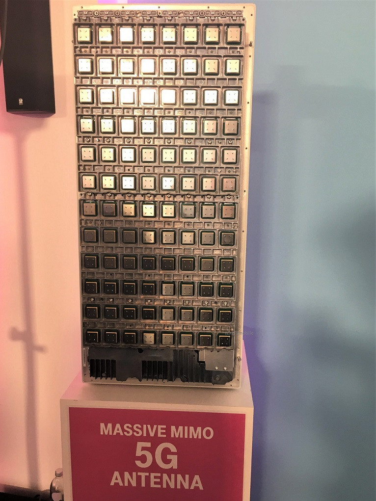
Massive MIMO uses many antenna elements with corresponding signal processing. Spatial multiplexing carries multiple data streams over the same time and frequency resources. It is distinct from beamforming, although both may operate within one antenna system.
The base station can also combine received uplink signals spatially. The benefit depends on the radio channel, antenna layout and available channel information, among other factors.
At higher frequencies, antenna elements become smaller for comparable electrical dimensions. Many elements can therefore fit into a compact area. Beamforming and multi-antenna techniques are used across several frequency ranges. Their performance depends on antenna layout, signal processing and the radio channel.
How transmit power and antennas work together
More transmit power can increase the link margin. The resulting range depends on antenna gain, alignment and other losses. The same power in watts can produce different conditions at the receiver when used with different antennas.
Small cells are often planned for specific, limited coverage areas. Extra sites can add capacity in busy locations. The coverage objective determines which type of cell is appropriate.
Why the device's return path matters
A smartphone may still receive the base station while its own return path has too little margin. Usable internet access requires both the downlink to the device and the uplink back to the network. Assess download speed, upload speed and latency together.

Devices differ in supported bands, antennas and power classes. A router may benefit from its placement, antenna arrangement or a suitable outdoor antenna. Transmit power follows the device and its power class. Its effect on range depends on the entire radio path.
Terrain, buildings and antenna height
A hill between the site and device can block the direct path. Buildings and vegetation add losses, while reflections and diffraction can create alternative paths. A circular coverage radius only roughly represents this environment.
A higher antenna site can clear obstructions. Height is planned together with alignment, downtilt, interference from other cells and the intended coverage area.
A connection can also cross several radio links. Integrated Access Backhaul (IAB) shows how chains of links bridge an overall distance in stages.
How to test reception at the intended location
- Use the intended combination: Test with the actual device, SIM and plan.
- Compare positions: A window, another room or a suitable outdoor position may offer different conditions.
- Measure both directions: Test download, upload and latency, ideally at different times of day.
- Use coverage maps for orientation: Test at the point of use to assess indoor reception.
For fixed access, apply these principles when placing the router. Our guide to indoor and outdoor 5G routers compares the signal paths and explains how to assess a location.
The original diagrams for comparison
The earlier range diagram and beamforming comparison remain available as historical documentation. Their distance and gain values are not carried forward as general performance figures.
Show the diagrams from the original article


Sources and assumptions
- LTEmobile: 5G range at different frequencies, source article; original material last modified on 1 June 2020.
- ITU-R P.525-5: Calculation of free-space attenuation, equation 6 used in the calculation.
- Ericsson Technology Review: Meeting 5G network requirements with Massive MIMO, beamforming versus spatial multiplexing and uplink/downlink effects.
- Ericsson: Massive MIMO for 5G networks, receive processing and channel information.
- Bundesnetzagentur: Mobile coverage, outdoor predictions and indoor differences.
- Umweltbundesamt, Texte 26/2023: Environmental assessment of mobile communication technologies, technical context for antennas and propagation.
Editorially revised test version dated 26 October 2026. The diagrams illustrate principles rather than measurements or actual network coverage. The original article on ltemobile.de remains unchanged.