LTE-Advanced: the technical background
LTE-Advanced was standardised in 3GPP Release 10. It develops LTE towards higher data rates, greater capacity and better cell-edge coverage. Its technical specifications follow the ITU's IMT-Advanced requirements. Major additions include Carrier Aggregation, enhanced multi-antenna techniques and relay nodes. [1] [5]
LTE-Advanced was designed for compatibility with LTE Release 8. An older LTE device can use a supported individual carrier in the evolved network. An LTE-Advanced device can also use the capabilities available in an older LTE network. The extra features become available when both network and device support them. [6]
The aim is to increase overall capacity and deliver high data rates to as many customers as possible. Individual devices can also use several carriers and spatial streams. The base station assigns available radio resources according to demand and radio conditions.
LTE technology covers the foundations of OFDMA, modulation and MIMO. EPC – the LTE core network explains how the base station works with the core.
Carrier Aggregation: combining bandwidth
A major development is combining available frequency carriers, known as Carrier Aggregation (CA). Each participating carrier is a Component Carrier (CC). They may lie within one frequency band or across several bands. [1] [3]
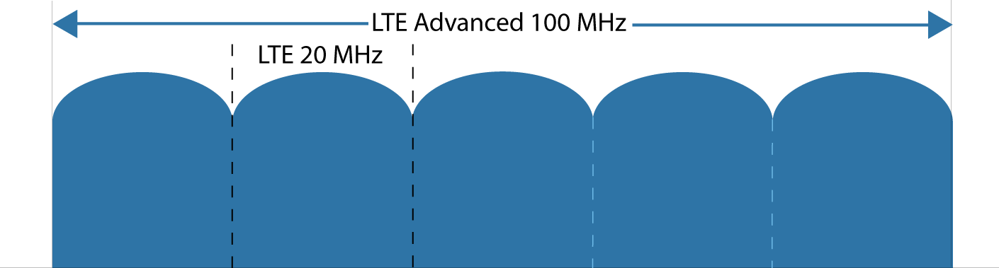
An individual LTE carrier is up to 20 MHz wide. Release 10 provides for up to five component carriers and a total of 100 MHz. Actual aggregation support depends on the band combination and device. There are three basic arrangements:
- Contiguous intra-band: Neighbouring carriers lie in the same band.
- Non-contiguous intra-band: Carriers lie in the same band with a frequency gap between them.
- Inter-band: Carriers from different frequency bands are combined.

Scalable bandwidths support different data rates. Two 20 MHz carriers, for example, provide 40 MHz in the direction being considered. With FDD, downlink and uplink bandwidths are counted separately. The number of aggregated carriers can differ between directions. [1]
The Primary Cell (PCell) handles central connection control. Other component carriers belong to Secondary Cells (SCells), which the network can activate and deactivate for data transmission. The combination in use can therefore change during a connection. Our frequency and band guide explains the ranges behind band numbers. [3]
MIMO: multiple spatial data streams
Release 10 expanded MIMO (Multiple Input Multiple Output) capabilities, supporting up to eight downlink and four uplink spatial transmission layers. Suitable antennas and signal processing are needed at both ends. [4]
Single-User MIMO carries several streams between a base station and one device. Multi-User MIMO (MU-MIMO) distributes spatially separated transmissions across several devices. Release 10 enhanced MU-MIMO techniques. The number of simultaneous streams depends on equipment and radio-channel properties. [4]
Relay nodes: a local cell with wireless backhaul
Relay stations, or Relay Nodes (RNs), are another important Release 10 addition. They are designed to improve coverage and provide good, fast connections near the cell edge.
A relay node connects over radio to a parent base station, the donor eNodeB. That connection provides its backhaul. The adapted LTE radio interface is called Un. Towards devices, the relay node provides its own LTE cell. [2]

A relay's proximity to devices can also improve indoor connections. This requires a suitable site and radio path. Device access and backhaul to the donor each need adequate resources, so capacity is planned for both links together. [2]
In 5G, Integrated Access Backhaul (IAB) provides integrated wireless backhaul for mobile cells. The IAB guide explains its architecture and the allocation between access and backhaul.
Spectral efficiency and data rates
Spectral efficiency measures transmitted data bits per second per hertz of bandwidth. The original requirement documents distinguish IMT-Advanced minimum requirements from the more ambitious LTE-Advanced development targets:
| Metric | Downlink | Uplink |
|---|---|---|
| IMT-Advanced: minimum peak spectral efficiency, ITU-R M.2134 | 15 bit/s/Hz | 6.75 bit/s/Hz |
| LTE-Advanced: target peak spectral efficiency, 3GPP TR 36.913 | 30 bit/s/Hz | 15 bit/s/Hz |
Peak figures assume error-free conditions and allocation of available radio resources to one device. In operation, data rates depend on channel bandwidth, modulation, spatial streams, signal quality and load. The requirements also place particular emphasis on average performance and cell-edge coverage. [5] [6]
What matters for phones and routers
- Band combinations: The device must support the network's CA combination. Technical documentation specifies the bands that can be combined and the number of carriers.
- Antenna capabilities: Usable MIMO techniques depend on base station and device capabilities as well as the radio channel.
- Location and load: An additional carrier becomes usable where its signal is strong enough. Antennas and surroundings therefore also affect possible aggregation.
Our radio-range guide explains propagation effects. For fixed access, the mobile router and FWA article covers placement, antennas and the home network.
The move to LTE-Advanced Pro
From Release 13, further LTE development is grouped under LTE-Advanced Pro. It includes enhanced carrier aggregation and Licensed Assisted Access (LAA), which combines licensed mobile spectrum with additional unlicensed spectrum. The network and device determine the features a connection actually uses. [7]
Early rollout and original diagrams
Combining existing LTE carriers was important in early Telekom, Vodafone and O2 rollouts. The historical LTEmobile infographic shows examples using 800 and 2,600 MHz, and 1,800 and 2,600 MHz. Its rates and operator assignments document that earlier period.
Open the historical infographic and original bandwidth diagram

Germany's EASY-C project, funded by the Federal Ministry of Education and Research, contributed to this research. It ran from April 2007 to September 2010. Test environments in Dresden and Berlin investigated cooperative antenna techniques and relaying, among other topics. [8] [9]
Sources and editorial review
Based on the LTEmobile article published on 6 October 2017 and last modified on 30 December 2019. The technical explanation was reviewed and updated on 26 October 2026. Historical diagrams and research history are identified as such. Technical statements draw on the following standardisation and research documents:
- [1] 3GPP: LTE-Advanced, Jeanette Wannstrom, May 2012
- [2] ETSI / 3GPP: TS 36.300 V10.4.0, sections 4 and 4.7
- [3] Rohde & Schwarz: LTE-Advanced carrier aggregation
- [4] 3GPP: LTE Release 12 – LTE Africa 2013, slide 4
- [5] ITU-R: M.2134 (2008), section 4.2: IMT-Advanced requirements
- [6] ETSI / 3GPP: TR 36.913 V10.0.0, sections 8 and 9
- [7] Qualcomm: LTE Advanced Pro, Release 13 and beyond
- [8] Fraunhofer HHI: EASY-C project archive
- [9] TU Dresden / Vodafone Chair: Field Trial Results for LTE-Advanced Concepts, 2010