LTE technology e-book
The LTE introduction offers around 40 pages explaining how LTE works and the properties of the frequency ranges used for it. This page presents extracts and additional explanations of the technical foundations.
Open the LTE technology e-book (free download, in German)
The German-language e-book dates from LTE's early years. It explains the foundations and documents development at that time. This article's explanations have been technically revised; the original e-book remains available unchanged.
LTE technical specifications at a glance
LTE stands for Long Term Evolution. 3GPP standardised its first stage in Release 8. The radio network is called E-UTRAN, and its base station is an eNodeB. It connects the device to the packet-based core network, the Evolved Packet Core (EPC). [5]
LTE supports scalable channel bandwidths of 1.4, 3, 5, 10, 15 and 20 MHz, allowing deployment in frequency blocks of different sizes. The operating band, operator spectrum holdings and network configuration determine the bandwidth used. These widths provide 6, 15, 25, 50, 75 and 100 resource blocks respectively. [1]
Maximum downlink data rates depend on capabilities. At 20 MHz, early LTE Category 4 achieves about 150 Mbit/s downlink and 50 Mbit/s uplink. Category 5 supports up to four downlink spatial streams and higher peaks. Categories 3 to 5 differ in supported rates and spatial layers: [3]
| LTE category Release 8 | Downlink | Uplink | Maximum DL layers |
|---|---|---|---|
| Cat 3 | Approx. 102 Mbit/s | Approx. 51 Mbit/s | 2 |
| Cat 4 | Approx. 151 Mbit/s | Approx. 51 Mbit/s | 2 |
| Cat 5 | Approx. 300 Mbit/s | Approx. 75 Mbit/s | 4 |
In operation, the base station shares available radio resources among active connections. A device's allocation depends on load, radio quality and data demand. LTE-Advanced extends these foundations through features including Carrier Aggregation, which allows a device to combine several LTE carriers.
Latency, mobility and cell capacity
Low latency is an important LTE advantage. The often-quoted figure below 5 ms refers to an original development target for one-way transmission of small IP packets across an unloaded radio-access network. Ping measures a round trip and also includes the core, transport network and path to the destination server. [4]
Mobility is another central requirement. LTE was optimised for speeds from 0 to 15 km/h and designed to operate at higher speeds. Original requirements considered connections up to 350 km/h and, depending on band and use case, up to 500 km/h. On fast trains, coverage along the route and handovers between cells are also important. [4]
Early cell-capacity requirements called for at least 200 active users with spectrum allocations up to 5 MHz. This describes support for active connections. Their traffic shares the available resources; light-traffic applications and large downloads place different demands on them. [4]
OFDMA and SC-FDMA: dividing the spectrum
Key LTE techniques include OFDMA in the downlink and SC-FDMA in the uplink. OFDMA means Orthogonal Frequency Division Multiple Access. Both techniques are based on OFDM and divide the available spectrum into many narrow subcarriers. [6]
OFDMA supports multiple users by allocating radio resources according to their requirements. The base station assigns resources in time and frequency, taking radio conditions into account. Ordinary LTE data transmission uses 15 kHz subcarrier spacing. Twelve neighbouring subcarriers across a 0.5 ms slot form a resource block. [2]
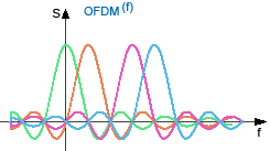
In OFDM (Orthogonal Frequency Division Multiplexing), individual carrier signals are orthogonal. Their spectra can overlap while remaining separable at the receiver, provided timing and frequency synchronisation are correct. A cyclic prefix provides protection against delayed components, for example those caused by reflections. [2] [6]
Narrowband interference affects a subset of subcarriers. Channel coding and error correction help the receiver reconstruct user data. With the same subcarrier spacing, a wider LTE channel contains more subcarriers and provides more radio resources.
SC-FDMA (Single Carrier Frequency Division Multiple Access) adds DFT preprocessing to OFDM. This produces lower uplink power peaks than ordinary OFDMA, allowing the mobile device's power amplifier to work more efficiently. That matters for battery operation and transmit power. [6]
Early descriptions also referred to LTE as HSOPA, High Speed OFDM Packet Access. WiMAX uses OFDMA too, and comparisons between the technologies featured prominently in early LTE discussions.
MIMO antenna technology
Another LTE building block is MIMO antenna technology. A system with several inputs and outputs is a MIMO system (Multiple Input/Multiple Output). In LTE, this means multiple transmit and receive antennas for wireless data transmission.
This can improve spectral efficiency, carrying more data over the same bandwidth, or improve transmission reliability. Multiple antennas at transmitter and receiver make use of the spatial dimension as well as time.
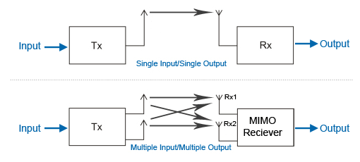
Spatial multiplexing transmits several streams simultaneously. The receiver separates them through their different radio paths. Usable layers depend on antennas, channel properties and the transmission mode selected by the network. Diversity uses several signal paths for more reliable reception. LTE-Advanced extends multi-antenna techniques. [5]
MIMO was also used in the UMTS evolution HSPA+ to achieve higher data rates.
Modulation: more bits per symbol
64QAM (quadrature amplitude modulation) is another way to increase LTE data rates. It varies the amplitudes of two carrier components with a 90-degree phase offset. Their combination produces distinct symbol states. Before channel coding, QPSK carries 2 bits per symbol, 16QAM carries 4 and 64QAM carries 6. [2]

Higher-order modulation needs a better wanted-signal-to-noise-and-interference ratio. The network adapts modulation and coding rate to measured channel quality. With greater attenuation or interference it selects more robust settings, reducing user data carried per radio resource. [5]
FDD-LTE and TDD-LTE
TDD (Time Division Duplex) and FDD (Frequency Division Duplex) are LTE variants that use spectrum differently. They were designed for deployment in unpaired and paired spectrum.
TDD-LTE uses the same frequency range for uplink and downlink, separating them in time. FDD-LTE uses paired spectrum: one range for uplink and another for downlink. Full-duplex operation allows simultaneous transmission in both directions. This flexibility accommodates national differences in spectrum availability. [2]

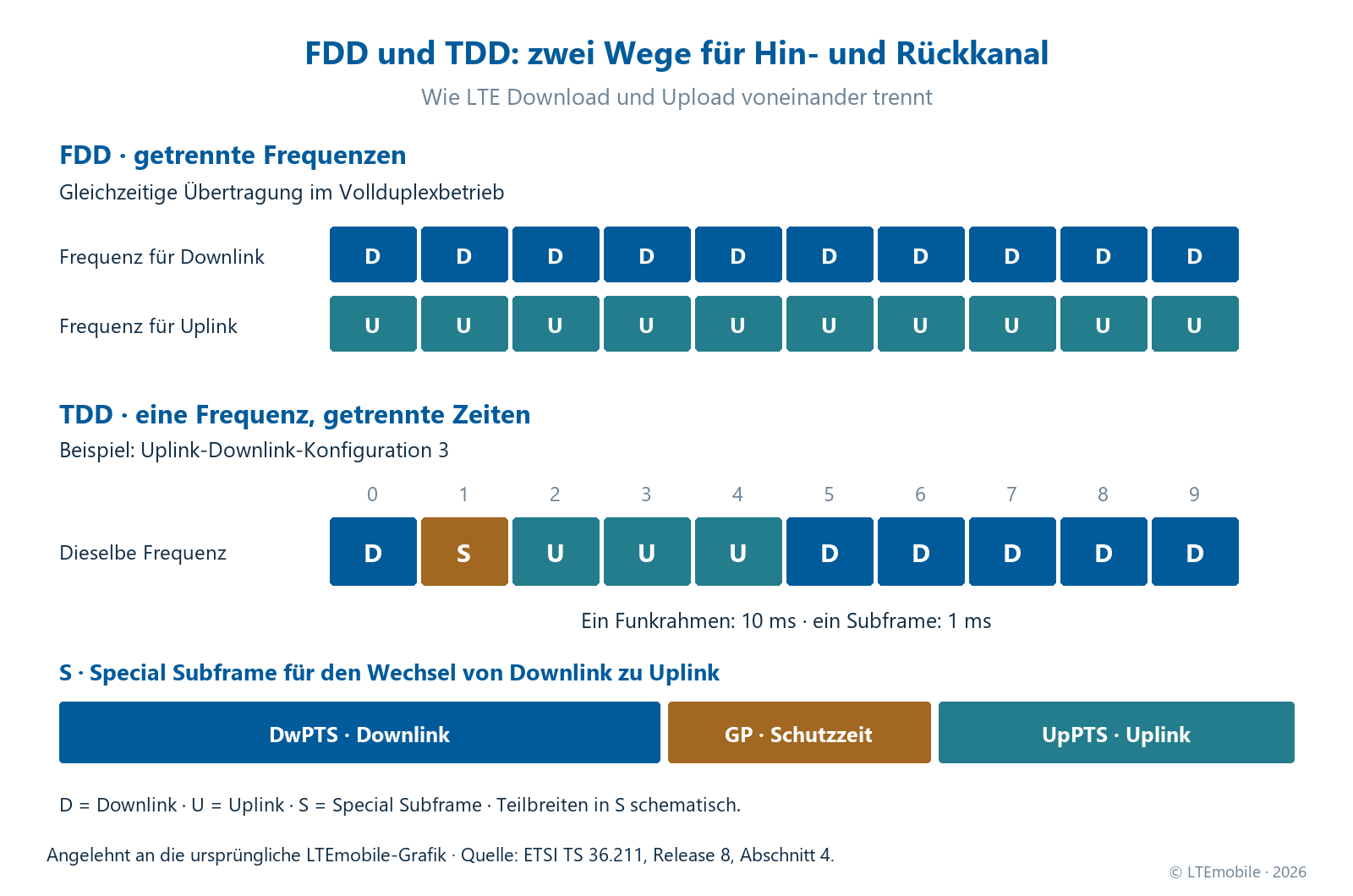
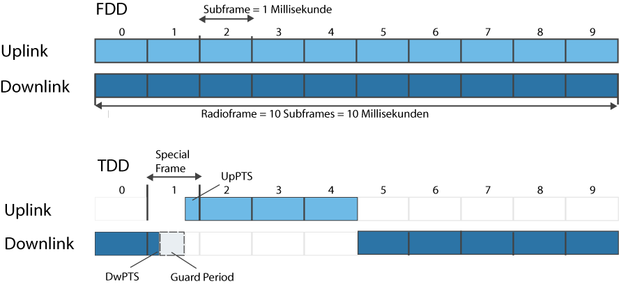
Both LTE variants divide transmitted signals into subframes. Each lasts one millisecond; ten form a 10 ms radio frame. The original LTE TDD structure defines seven uplink/downlink configurations, numbered 0 to 6. They determine the time allocation between the two directions. [2]
The downlink-to-uplink transition includes a special subframe with three fields: DwPTS (Downlink Pilot Time Slot), GP (Guard Period) and UpPTS (Uplink Pilot Time Slot). The guard period separates the two directions during switching and accommodates propagation and switching delays. Special-subframe length and allocation are configured separately. [2]
LTE upgrades and packet-based networks
LTE belongs to the evolution of the 3GPP cellular family, including GSM and UMTS. Its introduction brought an IP-based, packet-oriented architecture, facilitating shared transport of voice, video and data services and connectivity to other IP networks.
The LTE base station handles key radio-access functions and connects to the EPC. The core organises mobility, authentication and external data-network connectivity, among other tasks. LTE voice uses VoLTE (Voice over LTE) and the IP Multimedia Subsystem (IMS). EPC – the LTE core network explains the individual components. [5] [7]
LTE was designed to interwork with GSM and UMTS. A handover transfers an existing connection to another cell. Transitions between radio technologies require suitable network and device capabilities. To save energy, LTE includes DRX (Discontinuous Reception): the device pauses reception according to a timing pattern agreed with the network. [5]
LTE provides MBMS for broadcast-style services. In MBSFN operation, several synchronised cells send the same signal simultaneously, allowing many receivers to share one transmission of the same content. [5]
LTE-Advanced develops these foundations through Carrier Aggregation and enhanced multi-antenna techniques. Dynamic Spectrum Sharing (DSS) explains how LTE and 5G can share a frequency band.
Diagrams from the original article
The old data-rate table and original FDD/TDD illustration remain as documentation. The device-category table above and newly labelled duplex diagram explain the values in context.
Open the original data-rate table and FDD/TDD diagram

Sources and technical context
Based on the original LTEmobile LTE Technik article. Technical details were checked against the following primary sources as of 27 October 2026. Release 8 documents establish the original LTE foundations; the Release 10 system description covers evolved functions.
- [1] ETSI / 3GPP TS 36.101 V8.9.0 – LTE radio channels
- [2] ETSI / 3GPP TS 36.211 V8.9.0 – Physical channels and modulation
- [3] ETSI / 3GPP TS 36.306 V8.8.0 – LTE device categories
- [4] ETSI / 3GPP TR 25.913 V8.0.0 – Original LTE requirements
- [5] ETSI / 3GPP TS 36.300 V10.4.0 – LTE system description
- [6] 3GPP – LTE-Advanced, IMT-Advanced Evaluation Workshop 2009
- [7] GSMA – Voice over LTE
Further reading
- LTE Advanced – Carrier Aggregation, enhanced multi-antenna techniques and relay nodes.
- EPC – the LTE core network – how radio access connects to data networks and services.
- 5G frequencies and bands – frequency ranges, channel bandwidths and spectrum use.
- 5G range at different frequencies – how frequency, location and radio conditions interact.