At a glance
5G Non-Standalone (NSA) combines 5G radio with LTE and its Evolved Packet Core. 5G Standalone (SA) uses 5G New Radio and a dedicated 5G Core. The difference affects registration, the way data connections are managed and the services a network can provide.
You open a website, then make a call. Behind the scenes, the mobile network allocates radio resources, checks your access rights and forwards your data. With 5G SA, different network functions take on these jobs. We follow them from the smartphone to the core network.
O2 Czech Republic provides a recent example. On 12 November 2026, the operator announced that it had completed its SA upgrade across areas with existing 5G coverage. O2 also specifies a supported phone, suitable software and a compatible SIM. The announcement concerns its Czech network and shows how network deployment and support on an individual device fit together. [1] [2]

NSA: the LTE anchor coordinates the connection
The widely deployed NSA configuration combines LTE and 5G New Radio (NR). The smartphone establishes its anchor connection through an LTE base station. This base station coordinates the radio connection, while the Evolved Packet Core (EPC) continues to serve as the core network. An NR base station supplies additional radio capacity. This arrangement is called EN-DC: E-UTRA–NR Dual Connectivity. [5]
The user-plane path depends on the network configuration. Data can travel over LTE, over NR or through flows split between the two radio access links. Figure 1 shows an NR user-plane path using Option 3x. Our article EPC: how the LTE core network works explains the role of the LTE packet core. [5]
NSA allowed operators to introduce 5G in stages. They could add 5G radio while continuing to use LTE registration, mobility management and the existing EPC. [3]
SA: 5G radio access and a 5G Core
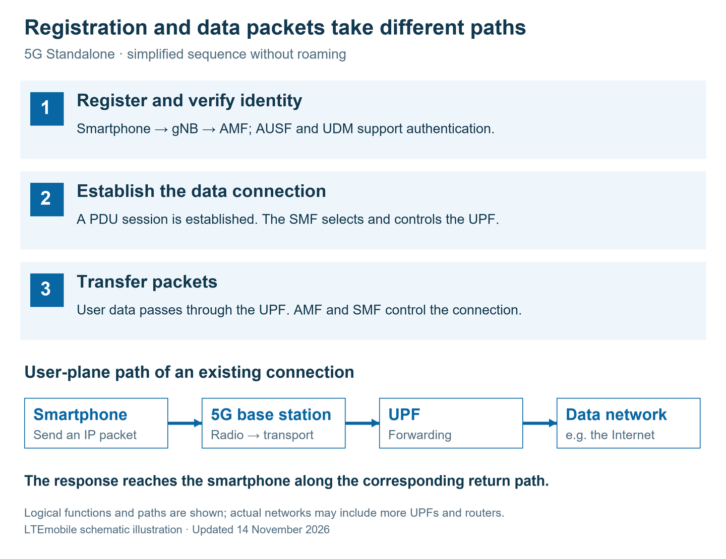
With 5G SA, illustrated here by Option 2, the NR base station connects directly to the 5G Core (5GC). Specialised network functions share the work. Broadly, they handle either control signalling or user-plane traffic. [4]
- AMF – Access and Mobility Management Function: manages device registration, reachability and mobility.
- AUSF and UDM: support authentication and the management of subscriber data.
- SMF – Session Management Function: manages the data connection and controls the UPF assigned to it.
- UPF – User Plane Function: processes and forwards user data between the radio access network and the data network.
This data connection is called a PDU session. It connects the device to a data network, such as the Internet or a corporate network. The division of roles helps explain the diagram: the AMF and SMF organise the connection, while the actual data packets pass through the UPF. [4]
Control functions in the 5G Core communicate through standardised services. This service-based architecture (SBA) makes it easier to combine functions for a particular application. Network slicing provides logical networks with specific characteristics on shared infrastructure, for example for different business services. The operator's offering determines which services a customer can use. [5]
What happens during registration and when you open a website
The smartphone first finds a suitable cell and establishes radio access. It sends its registration to the core network through the base station. The network checks its identity and access rights. After successful registration, the network can reach the device and manage its mobility. [6]
A PDU session is then established for Internet access. This configures the data network, session parameters and forwarding path. The SMF controls the UPF, while the radio network and device receive the information they need to carry traffic. When you subsequently open a website, its traffic uses this existing connection. [6]
In our simplified SA example, a packet travels from the smartphone through the gNB and transport network to the UPF, then on to the web server. The response follows the corresponding return path. The interactive model below lets you explore connection activation and packet transfer separately.
The technical detail: where SA can save time
Three processes determine when an application receives its response: activating the connection, waiting for radio resources and carrying packets to the service. The standards describe different procedures and measurements for these processes.
Direct NR access: in the NSA configuration considered here, the LTE base station coordinates the connection. TS 37.340 defines Secondary Node Addition for adding NR: request resources at the NR node, then configure the phone accordingly. In SA, the gNB can provide NR access directly. This simple SA configuration therefore avoids the additional LTE/NR coordination. In the NSA procedure, LTE can already carry data while NR is being added. [17]
Reusing stored context: alongside RRC_IDLE and RRC_CONNECTED, NG-RAN supports RRC_INACTIVE. The network and device retain the access context in this state. A resume procedure allows them to use it again, reducing the preparation needed compared with a complete new setup. The model presents a simpler comparison of the access architectures; its assumptions also explain the resume case. [18]
Preparing transmission opportunities: with dynamic allocation, the device waits for suitable resources. Configured grants let the gNB configure uplink resources in advance, so that the device can use the allocated transmission opportunities. NR also supports finer time grids: with a normal cyclic prefix, subcarrier spacings of 15, 30 and 60 kHz give slot durations of 1, 0.5 and 0.25 ms. These are NR radio features, used according to network and device support. NSA also uses NR. [18] [19]
Managing data paths and queues: the 5G Core can select a UPF close to the device and route traffic locally to a service. TS 23.501 describes this in Section 5.13. Individual flows also have QoS priorities and a Packet Delay Budget between the device and the UPF's N6 termination. These parameters influence resource allocation and packet handling. The operator's configuration and the distance to the service shape the result. [4]
The latency measurements described by 3GPP
| Measurement | Development target | What it covers |
|---|---|---|
| Control-plane latency | 10 ms | Transition from a power-saving state, such as IDLE, to the start of continuous data transfer. |
| User-plane latency for eMBB | 4 ms in each direction | Transfer across the radio interface, measured at the defined ingress and egress points of the radio protocols. |
| User-plane latency for URLLC | 0.5 ms in each direction | Target mean for radio transfer under the stated conditions. Reliability is a separate requirement. |
An Internet ping measures the round trip to a chosen destination. Its path includes radio, transport and core-network sections, plus the onward route. Connection activation and packet transfer over an active connection therefore need separate treatment. The values in the table are targets for the defined measurements; the 35 and 19 ms in the model below are illustrative application examples. [16]
Where the delay comes from
Response time consists of several contributions. On the radio link, the device waits for allocated resources; poor radio conditions can require retransmissions. Traffic then passes through site backhaul, routers and the packet core, continues to the server and is processed there. Load can also introduce queueing delays.
A suitably placed UPF and a nearby data network can shorten the route to a service. The following comparison uses an NSA scenario with a central connection point and an SA scenario with a closer UPF and a service reached through a shorter path. We keep radio and processing times equal to show the contribution made by the shorter connection. [4]
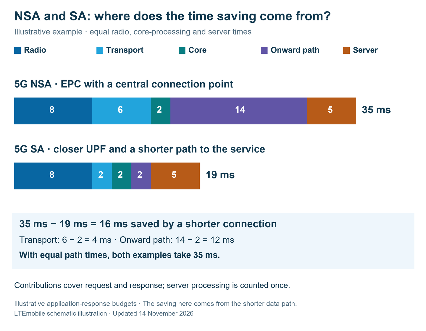
The diagram uses 35 ms for the NSA example and 19 ms for the SA example. These illustrative time budgets describe a small request and response over an active connection. The 16 ms saving comes from 4 ms less in transport and 12 ms less on the onward path to the service. Radio, core processing and server time stay the same.
Interactive · two networks, one shared clock
When does the response reach the phone?
Both packets start together. Follow the request to the server and the response back to the phone.
Central connection point · control via LTE anchor
- Phone
- 5G NR
- EPC
- Server
Ready at the phone.
Closer UPF and a shorter path to the service
- Phone
- 5G NR
- UPF
- Server
Ready at the phone.
Numbers and bars show the full time contributions in milliseconds. The fill shows the share already completed. Both directions are included; server processing is counted once.
Ready: both packets start at the phone.
Calculations and model assumptions
NSA: 8 + 6 + 2 + 14 + 5 = 35 ms.
SA with a closer connection: 8 + 2 + 2 + 2 + 5 = 19 ms.
The numbers are illustrative and match Figure 3. The model shows a small request and response over an active connection. Each network contribution is split equally between the outbound and return paths, with server processing in between. The animation runs 200 times slower than model time.
The difference in this example comes from where the network exit and service are located. “Equal paths” assigns the same values to both networks. Radio configuration, load, packet size and server performance stay equal. The NSA user-plane path shown here runs over NR (Option 3x). The LTE anchor handles control tasks; the diagram shows user data. Node spacing is schematic, and additional routers and tunnels are grouped together. The display represents an application response. Actual times depend on the particular network and service.
Signalling · schematic sequence
From inactive radio access to NR data transfer
The phone is already registered and its core-network data connection exists. Radio resources and the user-plane path are now activated.
Starting point · radio access inactive
The subscriber is known to the EPC. LTE and NR are not carrying user data at this starting point.
The device is registered with the 5G Core. Its PDU session exists, but radio transmission is inactive.
We are activating an existing data connection. Initial registration and the creation of a new PDU session took place earlier.
Dashed orange: signalling · Blue or teal: user-plane path. Each step groups several messages. Their order supports the comparison; the animation has no millisecond time scale.
The 3GPP procedures behind the model
NSA: LTE access and EPC service activation, followed here by adding NR according to TS 37.340, Section 10.2.1. Resources are requested at the NR node and the phone is configured accordingly. LTE can carry user data before NR is added.
SA: NR access and activation of the user-plane path for the existing PDU session; see TS 38.300, Section 9.2, and TS 23.502, Section 4.2.3. The illustrated gNB access avoids additional LTE/NR coordination.
The diagram groups service requests, security handling, radio-bearer configuration and path activation. Messages can overlap in an actual network. RRC_INACTIVE has its own resume procedure with stored context. Radio load, DRX and the network configuration affect actual activation times.
Standards: TS 37.340 [17] · TS 38.300 [18] · TS 23.502 [6]
Selecting “Equal paths” gives SA the same 6 ms transport contribution and 14 ms onward-path contribution as NSA. Both responses then arrive after 35 ms. SA enables a different organisation of the core network; the practical latency benefit depends partly on where the network exit and service are located. An EPC can also be designed for local data paths. Telenor Open Lab [15] explains the principle of a local UPF.
In practice, it helps to consider data rate and response time separately. Data rate describes how much data travels per unit of time; latency describes delay. Our article on 5G frequencies and frequency bands explains the available frequencies and channel bandwidths.
Phone calls: VoNR and the move back to LTE
Modern mobile networks use the IP Multimedia Subsystem (IMS) for phone calls. It handles tasks such as registration with the voice service and call setup. With Voice over New Radio (VoNR), the 5G radio access network and 5G Core carry the voice packets. The device and network must support the service and be configured to use it. [7]

With EPS Fallback, the phone initially registers on SA. When a call is set up, the network triggers a move to LTE under the conditions specified for this procedure. The call then uses VoLTE. Device capabilities, network configuration and radio conditions influence this decision. The additional change can lengthen call setup. [8]
You may see the display change from 5G to LTE during call setup. Device diagnostics or the operator's documentation provide a more reliable way to identify the voice service in use. For a data-only router, the data connection takes priority; voice features need checking for the particular model.
Practical checklist: using SA with Telekom, Vodafone and O2 in Germany
These examples show how to move from a device name to a usable SA connection in Germany. Each starts with a specific network-operator offering. For plans sold by another provider on the same radio network, check that provider's own SA access rules.
| Network and device example | What you need | What to do |
|---|---|---|
| Telekom · iPhone 15 Example: FaceTime with 5G+ Ultra | A MagentaMobil plan from the generation launched on 1 August 2024 or later, plus the free 5G+ Ultra option. The iPhone 15 appears on Telekom's device list. | Activate the option in the MeinMagenta app, update the phone's software and use FaceTime where 5G+ coverage is available. Telekom lists iPhone 15 and later for video calls; cloud gaming has its own partner and device requirements. [10] |
| Vodafone · Samsung Galaxy S23 Example: smartphone with Giga 5G+ | A 5G-enabled plan, a supported SIM and the free Giga 5G+ option. Vodafone explicitly lists the Galaxy S23 series as a device example. | Check or activate the Giga 5G+ option in the MeinVodafone app. Then establish a data connection in a covered area with current device software and 5G enabled. [11] |
| O2 Germany · Galaxy S24 or Google Pixel 9 Example: O2 Mobile with 5G Plus | A suitable 5G-enabled O2 contract with 5G Plus activated and a compatible SIM. Both devices appear on O2's moderated list. | Activate the free option in Mein O2. O2 checks SIM compatibility and sends a text message if the SIM needs replacing. Use the devices with current software. [12] [13] |
| O2 Germany · Zyxel NR2301 Example: mobile 5G router | The NR2301 appears on O2's router list, and Zyxel confirms SA and NSA support. Pair it with a SIM whose specific plan has 5G Plus access enabled. | First check plan and SIM eligibility in Mein O2. Update the router software, inspect the mobile-network settings in its web interface and test a connection where you intend to use it. [13] [14] |
Check the router's plan name: O2 excludes its O2 Data plans from activation in the linked 5G Plus FAQ. For the NR2301, using a SIM with actual SA access is therefore essential. Hardware support and contract eligibility need separate checks. [12]
Then check the connection:
- Confirm activation: check MeinMagenta, MeinVodafone or Mein O2 to see whether the correct option is active for that exact number. For the Telekom example, also use the supported application.
- Read the connection mode: look for an explicit entry such as NR SA or Standalone in available diagnostics or connection information. NR NSA or EN-DC indicates an LTE anchor. The ordinary status display may simply show “5G” in either case. [11] [12]
- Test your own use case: make a smartphone call and check the voice mode. For a router, compare data rate and response time at the intended location at different times of day. These measurements show how the connection performs there.
When choosing a router, also check its ports, antenna options, Ethernet speed and Wi-Fi capabilities. Our article on 5G routers covers these details. Use the 5G Router Finder to compare models for a particular use case.
How SA relates to 5G-Advanced
5G-Advanced starts with 3GPP Release 18. It develops the radio network and system features further. 5G Americas describes an SA core as a requirement for full access to the enhanced features, alongside requirements for radio, transport, operational support and devices. What a particular network provides depends on its implementation and supported devices. [9]
For any advertised feature, ask a specific question: does it involve additional radio carriers, a local service, a particular voice mode or an approved application? That identifies which parts of the network and device need to support it.
Sources and editorial notes
Updated: 14 November 2026. The O2 announcement concerns the Czech Republic. The four diagrams and interactive model are simplified LTEmobile illustrations. The times in Figure 3 and the model form a fictional worked example. The packet animation splits path contributions equally between the outbound and return directions and runs 200 times slower than model time. The separate connection-activation view groups signalling procedures without a time scale. Each 3GPP target is presented with its measurement definition.
- O2 Czech Republic: press release of 12 November 2026
- O2 Czech Republic: requirements and supported phones
- Ericsson: 5G Standalone and comparison with NSA
- 3GPP TS 23.501 V18.6.0 (July 2024): system architecture, particularly Sections 4.2.3 and 6.2
- NTT DOCOMO: Overview of 5G Core Network Technologies for 5G SA, Technical Journal Vol. 24 No. 4
- 3GPP TS 23.502 V15.17.0 (September 2023): registration, PDU sessions and EPS Fallback, Sections 4.2.2.2, 4.3.2.2 and 4.13.6.1
- Ericsson: 5G voice network evolution, 2025 edition, particularly PDF pages 6–8
- ETSI TS 103 905 V1.1.1 (November 2024): VoNR and VoLTE, interworking and EPS Fallback
- 5G Americas: 5G-Advanced Overview, July 2025, particularly PDF page 7
- Telekom: 5G+ Ultra – devices, plan requirements and supported applications
- Vodafone: 5G plans, Giga 5G+ option and device examples
- O2 Germany: 5G Plus FAQ – plan and SIM eligibility
- O2 Germany: moderated list of 5G Plus smartphones, routers and tablets
- Zyxel: NR2301 – manufacturer specifications for SA/NSA support and web management
- Telenor Open Lab: Local Breakout Edge – local UPFs and shorter data paths
- 3GPP TR 38.913 V18.0.0 (May 2024), Sections 7.4 and 7.5: definitions and latency targets
- 3GPP TS 37.340 V18.7.0 (April 2026), Section 10.2.1: EN-DC and Secondary Node Addition
- 3GPP TS 38.300 V18.3.0 (October 2024), Sections 9.2 and 10.3: RRC states, resume and uplink scheduling
- 3GPP TS 38.211 V19.2.0 (February 2026), Sections 4.2 and 4.3.2: numerology and slots