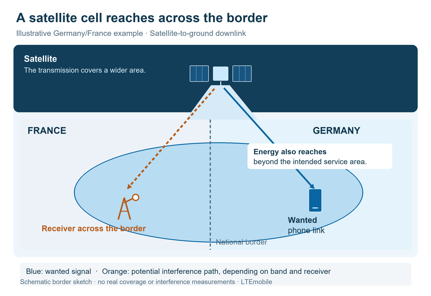
On a country road near the German–French border, a message sits in a phone’s outbox. The next village is across the river; the phone’s own mobile mast is behind a ridge. A satellite could take over the connection. Its transmission also reaches French territory, where other operators use spectrum and other radio services need to keep working reliably.
This is an illustrative scenario. It captures a central question for direct-to-device services: how can a satellite connect a phone while protecting radio services in the neighbouring country? The footprint on the ground, the characteristics of the receivers and the rights to use the spectrum all have to fit together.
Why spectrum is on the agenda now
The Mobile Network Innovation Summit scheduled its virtual MNIS:NTN event for 3–4 November 2026. The programme included the spectrum debate ahead of the 2027 World Radiocommunication Conference. A preview published by 5GTelecoms.Space announced a 4 November session with GSOA, Ofcom and the GSMA. This article draws on the published programme and the 2 November preview.
The technology connects satellites directly to mobile devices. One approach uses spectrum already allocated to mobile-satellite services and devices designed for it. Another brings satellites into bands used by terrestrial mobile networks. This second approach brings satellite and mobile operators’ spectrum plans together. Our guide to Direct-to-Cell, Direct-to-Device and 5G NTN explains the architectures.
A satellite beam has a spatial antenna pattern
Satellite antennas can concentrate transmit power in particular directions. On the ground, this produces a footprint, often called a spot beam. Received power varies within that area and outside its centre. Antenna sidelobes also contribute to the distribution of radio energy. Planning therefore needs to account for the antenna pattern and the power radiated in each direction.
An operator can control where devices are allowed to connect. That access control governs the service offered to users. Protecting a receiver in France also depends on how much energy reaches it and how its antenna and receive filters respond. Ericsson’s technical overview discusses, among other aspects, geographical separation between terrestrial and satellite operation in mobile spectrum.
Germany/Luxembourg: when a hillside blocks the path
Along the Moselle, Sauer and Our rivers, terrain adds another dimension to the example. Imagine a phone on a road in a border valley. The nearest suitable mobile site is behind a hillside. For the satellite link, the direction from which the signal arrives now matters.
When the satellite is low on the phone’s horizon, the hillside can block the direct radio path. A position higher in the sky may provide a clear line of sight. With low-Earth-orbit satellites, the geometry changes during a pass; the network can also switch between satellites. A narrow opening onto the sky limits the available paths.

A fixed-link receiver on higher ground may have a clear view in the same direction. Poor reception at the phone and potential interference at that receiver can therefore arise under quite different conditions. A compatibility calculation needs separate site, terrain and antenna data for the two radio paths.
Cross-border coordination is tangible here too. Luxembourg’s ILR lists bilateral and multilateral spectrum agreements with neighbouring countries. These include an agreement for terrestrial mobile networks in the 1,920–1,980 and 2,110–2,170 MHz bands. It provides an existing coordination framework for networks on the ground. The conditions for an additional satellite service need to be assessed separately.
What WRC-27 is being asked to decide
Under agenda item 1.13, WRC-27 will consider possible additional allocations to the mobile-satellite service for direct connectivity to IMT user equipment. IMT is the ITU’s name for the family of International Mobile Telecommunications systems. Studies cover suitable bands between 694/698 MHz and 2.7 GHz. This defines the range under investigation, from which possible allocations may emerge. See the ITU’s WRC-27 agenda overview.
The mandate is set out in WRC-23 Resolution 253. It includes sharing and compatibility studies with existing services, including in adjacent bands. It also calls for studies of technical and operational measures to ensure that satellite stations do not cause harmful interference to, or claim protection from, stations in the mobile service.
As of 7 November 2026, the outcome remains open. The conference can change the international spectrum framework and associated rules. The bands and conditions eventually adopted will depend on the studies and negotiations.
Why 2,110–2,170 MHz is a useful example
A specific contribution is listed by the ITU as Working Party 4C, Document 802. Its public entry identifies satellite downlink operation in 2,110–2,170 MHz and compatibility with the incumbent terrestrial fixed service. Submitted by Iran, the contribution is dated 23 September 2026. See the public ITU document entry.
The full text is restricted to ITU TIES users. The public entry establishes the topic, frequency range and origin of the contribution. It does not reveal the numerical results or any separation distance derived from them. The explanation below describes the underlying assessment method.
The band is also familiar from terrestrial mobile networks: it covers the downlink of LTE Band 1 and 5G band n1. The services that need protection at a particular location depend on the applicable allocations and assignments. The fixed-link receiver in our illustration is a model. A site-specific assessment needs the actual channels and antennas in use.
How a fixed-link receiver picks up the satellite signal
1. Frequency and receiver bandwidth
The receiver is tuned to a particular channel. Satellite energy falling within its receive bandwidth can be processed alongside the wanted signal and make that signal harder to detect. For adjacent channels, out-of-band emissions and the receiver’s filtering work together. The assessment therefore considers the complete transmitter and receiver systems.
2. Arrival direction and antenna gain
A fixed-link antenna receives most strongly from the direction of the other end of its link. A satellite signal arriving from a similar direction can also be picked up strongly. Larger angles from the antenna’s main receiving direction change the effective gain. Sidelobes and backlobes remain part of the pattern. ITU-R F.699 provides reference patterns for coordination studies where suitable assumptions are needed.
3. Power, aggregation and time
The energy arriving at the ground is often described by power flux density, expressed per unit area and, where relevant, per unit bandwidth. Combining it with the antenna’s direction-dependent receiving capability and receive-path losses gives the interference power at the receiver. The quantities must use consistent bandwidths and reference points.
The interference power I can then be compared with the noise power N. The I/N ratio describes the additional interference relative to receiver noise. Duration and frequency of occurrence matter too. Several visible satellites or transmissions can contribute power at the same receiver. ITU-R F.758-8 covers system parameters and protection criteria for fixed-service studies of this kind.
As a satellite moves, its distance, arrival angle and the receiving antenna’s gain in that direction change throughout the pass. The calculation has to represent that geometry. A brief period with an unfavourable angle and a sustained increase in interference may therefore require separate assessment.
Measures that can protect the neighbouring network
This assessment points to several technical controls. The combination that works for a particular system must be demonstrated using its parameters and the requirements of the services being protected.
| Measure | Effect near the border | What still needs assessment |
|---|---|---|
| Footprint design and beam steering | Concentrate power in authorised areas and reduce illumination in affected directions. | Antenna patterns, sidelobes and changing geometry during a pass. |
| Power limits | Reduce the energy arriving at the ground and the resulting interference contributions. | Aggregate simultaneous transmissions, with consistent area, bandwidth and time references. |
| Frequency and channel planning | Separate links geographically or in frequency, and avoid sensitive combinations. | Protection in the wanted channel and adjacent bands, and existing assignments. |
| Service areas and operating geometry | Restrict operation in particular areas or under particular viewing conditions. | How much border-area coverage remains under those restrictions. |
| Coordination and operational intervention | Agree parameters, points of contact and procedures for resolving interference. | Evidence, monitoring and mitigation that can actually be implemented. |
The UK provides an example of a national framework already set out: Ofcom’s D2D approach includes aggregate power-flux-density limits, a minimum satellite elevation angle of ten degrees and coordination conditions. For cross-border interference, it describes cooperation with neighbouring administrations. These UK conditions show how protection can be implemented through national authorisation; they apply within that framework.
Who brings the responsibilities together
| Level | Role | What it means for the border example |
|---|---|---|
| ITU / World Radiocommunication Conference | Set the international Radio Regulations framework, service allocations and associated procedures. | Establish a framework for possible additional satellite use while taking existing services into account. |
| European coordination | Prepare common positions and harmonised conditions where the relevant processes apply. | Neighbouring countries can work towards common technical foundations. |
| National spectrum administrations | Manage national spectrum use and required authorisations, and coordinate with other administrations. | Germany’s Bundesnetzagentur, Luxembourg’s ILR and France’s ANFR have relevant roles; ANFR handles French border coordination. |
| Mobile and satellite operators | Plan the system, demonstrate compatibility and comply with authorised parameters. | Implement protection through beam steering, channel planning, power control and operating procedures. |
For satellite-network frequency assignments, the Bundesnetzagentur lists requirements including the national frequency plan, national coordination and international coordination of the satellite system. ANFR describes its international border-coordination role. The 2017 agreement for the 2.1 GHz bands illustrates how neighbours already agree conditions for terrestrial networks.
How potential interference is investigated
Investigators compare observations at the affected receiver with actual network operation. When did the interference occur? Which channel was affected? Which satellite and beam were active at the time? How were the antenna and receive path aligned? Measurements and operational logs help narrow down the possible causes.
In Germany, the Bundesnetzagentur’s radio monitoring and inspection service checks spectrum use and investigates interference. Its space-service monitoring facilities include the Leeheim satellite monitoring station. A cross-border case requires the administrations and operators involved to combine their findings. Ofcom’s framework explicitly describes investigations with neighbouring administrations and, where necessary, action against the licensee.
Useful information for a report includes the location, time, affected equipment and a clear description of the fault. The Bundesnetzagentur explains its procedure on its radio-interference page. For a mobile connection problem, the service provider is the first point of contact to help distinguish coverage, device and network issues.
What this means for a phone in a border valley
Several conditions have to hold at once for the phone on our border road: a usable radio path, a suitable service, a compatible device and operation within the authorised parameters. In the Luxembourg-border valley, the path over the hillside matters too. At the French border, the system must likewise stay within the permitted interference levels for receivers on the other side.
Satellites can provide additional connections where the terrestrial radio path is unavailable or fails. How close to a border that extra service can operate depends on antennas, terrain, power and coordinated conditions of use. Together, these determine how a broad footprint becomes a connection that people can reliably use.
Further reading on LTEmobile
- Direct-to-Cell, Direct-to-Device and 5G NTN: architectures and differences
- Satellite connectivity on phones: what actually works in Germany?
- 5G frequencies and bands
- 5G range at different frequencies
- LTE availability: understanding coverage and reception
Sources and scope
Information checked as of 7 November 2026. The border scenarios and diagrams are original explanatory examples. They use no actual site, measurement or coverage data. Only the publicly visible catalogue information was used from the restricted ITU Contribution 802.
- MNIS:NTN — published programme, 3–4 November 2026
- 5GTelecoms.Space — preview of the spectrum session, 2 November 2026
- ITU — WRC-27 agenda overview, particularly item 1.13
- ITU — WRC-23 Final Acts, Resolution 253, printed pages 490–492
- ITU WP 4C — Document 802, public entry; full text restricted
- Ericsson Technology Review — Satellite direct to device: 4G or 3GPP NTN?, 11 December 2025
- ILR — spectrum coordination agreements with neighbouring countries (French)
- 2017 multilateral agreement — terrestrial networks in 1,920–1,980 / 2,110–2,170 MHz
- ITU-R F.699-9 (02/2026) — reference antenna patterns for fixed wireless systems
- ITU-R F.758-8 (02/2025) — fixed-service system parameters and compatibility criteria
- Ofcom — D2D authorisation framework, 9 December 2025, especially sections 2.9 and 3.40–3.47
- Bundesnetzagentur — satellite networks and frequency-assignment requirements (German)
- ANFR — border-coordination responsibilities (French)
- Bundesnetzagentur — radio monitoring service and Leeheim satellite monitoring station (German)
- Bundesnetzagentur — identifying and reporting radio interference (German)